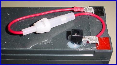
I've put in some time designing yet another system. This one is smaller, faster turning and cheaper to construct than the previous versions. It is also only built to handle a backer the size of a 50 foot target or the repair center for full sized outdoor targets. This design is totally different from my previous turning systems so all aspects will be changed for its construction, other than the battery connection. This smaller system still runs from 12 volts, but doesn't require the current capability of the larger units. Again, this unit will be built to either be mounted on a tripod or mounted to a different support structure. There is a minimal drain during Face and Edge times and a short burst of current during each turn.
The heart of this system is a power door lock actuator. The units started showing up for as little as $5.00 in surplus sales areas. My initial trials with this motor resulted in disappointment from many of them burning up. For this reason I designed a circuit to supply only a short duration of current to the motor for each swing. I had to work a balance between enough current to complete the swing and to charge capacitors, while making sure I didn't create an inappropriate reverse current. Unfortunately, this makes the turner unreliable at face times less than two seconds. With additional circuitry I could probably correct this, but I'm not working that right now.
This target system is designed to be faced and edged by a short supplied to the appropriate connection of a stereo connector. The short has to be supplied long enough that the turn is completed, yet must also be removed long enough for the appropriate capacitor to fully charge. The Face signal is supplied between ground and the Face Input while the Edge signal is supplied between ground and the Edge Input. Such a signal is provided by my Rangebox, a command playback and switching controller powered by a 9-volt battery.
I have built several versions of turners, and decided to place this information into the public domain so others can build them. If I can provide a means for someone to afford a turning system, then I'm happy to have published this page. If help or more information is needed, contact me (15 Lakeview Ave, Tupper Lake, NY 12986).
Of course, no printed instructions can be free of a safety reminder these days. Due to the inability of me to be by your side through this, you will need to assume all risk involved with the construction and/or use of this system. This includes, but is not limited to, the use of all tools involved. Additionally, this system has moving parts! Be aware of the pinch points and swing position of the frame when using it. The battery should only be connected while you are not within the reach of the turning parts. Disconnect the battery at any time you are within the swing radius, to include dis/connecting the control cable.
Feel free to provide feedback on how this project has worked. I will try to change it if better parts appear or techniques evolve. I have reviewed this document countless times, but there is no guarantee of accuracy. If an error is found, I will attempt to promptly get the correction posted. Please feel free to send me comments.
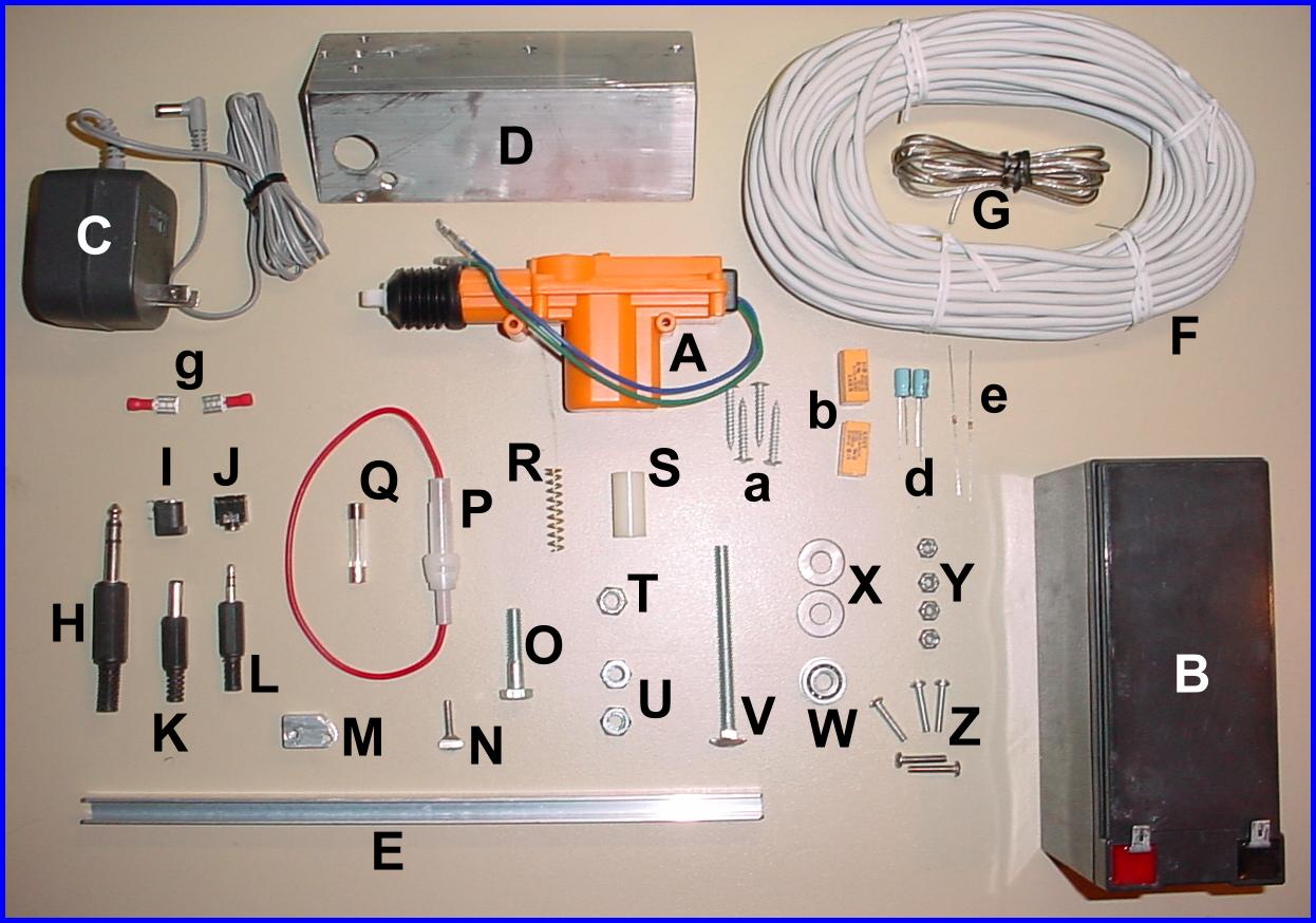
Let's start with a picture and table of all the parts necessary to construct the turner using the following description. Substitutions can be made for many of the parts, especially connectors. The following should really be considered an outline to guide you through building a turner constructed to your needs.
| Description | Comments | A | Door lock actuator | All Electronics type DLA-1 or DLA-2 or equivalent **NOTE: Some of these units have a swivel type connection piece - they are 1/2" longer and need appropriate adjustments to the mounting dimensions. | B | Battery | 12 volt sealed lead acid | C | Charger | 12 volt DC - this connector determines items I and K and also the polarity of the battery wiring | D | Bracket | 2" angle x 1/8" thick x 6" long | E | Channel | 1/4" inside by 10.5" long | F | Cable | at least three conductors ~60 feet in length | G | wire | two conductor wire for power connection - about 5' long | H | Connector | appropriate connector for controller - shown is a 1/4" stereo plug used with the Rangebox controller | I | Connector | connector for battery to mate with connector on charger | J | Connector | used for control cable connection to circuit - shown is a 1/8" stereo jack | K | Connector | connector to supply power to circuit - mates with item I | L | Connector | connector for cable to mate with item J - shown is a 1/8" stereo plug | M | Link | connecting link from actuator to crank - made from 3/4" piece of channel metal - same material as item E | N | Thumbscrew | 6-32 paddle handled 1/2" thumbscrew | O | Bolt | 1/4-20 x 1-1/4" hex bolt | P | Fuse holder | should be chosen based on fuse type desired | Q | Fuse | should be determined by testing | R | Spring | this spring will probably have to be adjusted for proper working - I didn't find a stock one | S | Spacer | nylon spacer 1" high x 1/4" ID x 1/2" OD | T | Lock nut | 1/4" nylon insert lock nut | U | Hex nuts | standard 1/4-20 hex nuts | V | Carriage bolt | 1/4-20 carriage bolt - will be cut to less than 1" and two portions of the head will be trimmed to fit in channel | W | Bearing | 1/4" ID x 1/4" width x 11/16" OD with flange | X | Flat washers | standard 1/4" flat washers | Y | Lock nuts | 6-32 nylon insert lock nuts (I use an optional fifth nut - only four shown in picture) | Z | Machine screws | 6-32 x 3/4" slot head screws | a | Screws | mounting screws for motor and circuit board | b | Relays | needed are one DPDT and one SPDT 12 VDC - shown are two DPDT which I use | d | Capacitors | value determined by experimentation | e | Resistors | value determined by experimentation | g | Terminal connectors | size determined by battery terminals |
The first item needed is a six inch piece of angle metal, 2 inches each side by 1/8 inch thick. Choose an end to work with. Squareness isn't a necessity, but you will need to reference from a point on the chosen end. Place the bracket in front of you such that the chosen end is to the left and the center seam is facing up; kind of like looking at a tent from the side. Measure 11/16 inch in from the left and make a mark. Using a square, extend this mark across both flats so that it carries from the front edge, over the center and down to the back edge. Now Measure and mark at the following points on the line:
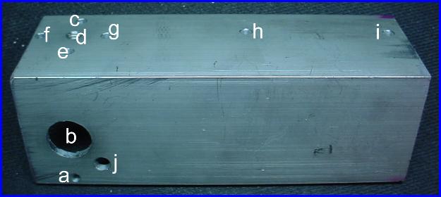
** These holes (c, d, e) are for mounting on a tripod shoe and are optional
Next, mark the following points, not along the previous line:
**Again, these holes (f, g) are for a tripod shoe and are optional. If they are used, the five marks should form a diamond pattern with holes c, e, f and g around hole d.
****These holes will be dependent on the motor used and the link length. You may need to wait until final assembly to determine their positions. Or, if able, you might want to create slots to allow for final adjustment. In either case, expect to adjust the motor mounting.
Now for something different. Since the location of this last hole is somewhat critical in relationship to the hole for the bearing (b), we will use that mark to determine this last hole's placement. Locate the second mark from above (b) that was placed at 15/16 inch from the front edge along the line. Make a second line at 45 degrees from the original line passing through the 15/16 inch mark (b) and travelling toward the front edge, but away from the chosen end. Looking at the bracket in the above orientation, this line should proceed down and right away from the 15/16 inch mark (b). Place a mark (j) 11/16 inch from the 15/16 inch mark on this new line.
Now that all the marks are determined, the holes can be drilled. I used the following size drill bits for the referenced holes:
After all drilling is complete, tap hole d to 1/4-20 for use with a standard tripod shoe.
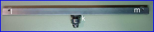
The first thing we need for the frame is the 10-1/2 inch long 1/4 inch inside channel metal. Let's orient it crosswise with the open edge facing up for future reference. Make three marks for drilling at these locations:
Use the 1/4 inch bit for the center hole (k) in the bottom and the 9/64 inch bit for the holes near the ends (l, m).
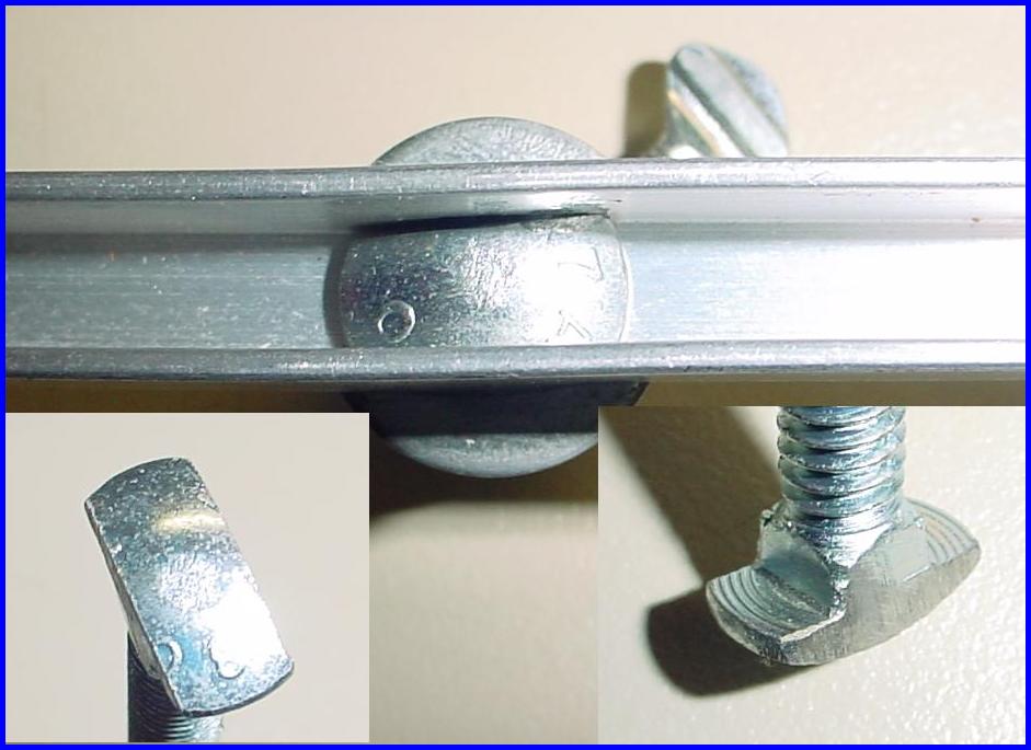
Next get the carriage bolt and cut two opposite portions off the head such that the cuts are in line with two opposite sides of the square shank area under the head. What we're doing here is reshaping the head to 1/4 inch wide so it will fit into the channel. Once you have the head shaped to fit the channel, place the bolt through the center hole (k) such that the head is inside and the threads protrude out of the bottom flat. Now slip something like a socket over the bolt and using an appropriate nut and wrench, tighten the nut until the bottom edge of the remaining head is flush with the inside of the channel. This should pull the square portion of the shank through the channel. Once you've reached flush, remove the nut and socket, then file, grind or cut enough metal around the area so that two 1/4 inch flat washers can freely fit flush with the channel. When everything is cleaned up, place the two washers and a nut on the bolt and tighten.
Now for something a little bit more detailed, we're going to add the bearing and a nylon sleeved lock nut to the bolt. You might be able to do this with a standard nut, but I use a lock nut because it is taller, so it has more surface area for the hole we'll be making. Tighten this lock nut down against the bearing and take notice of its orientation. We're going to need to line up one of the sides to be 45 degrees off angle from the channel. But of course, there's a little more to it. With the channel horizontal and the open edge away from us, we need the two flats that are facing 45 degrees from the horizontal edge of the channel to be facing such that the hole we drill will go from botom right to top left. Do this by tightening until you get a flat surface where it needs to be. This can be a bit off, but the closer, the better. Once you get it tightend down properly, mark a point to drill near the center of the flat. Next, find a way to cover the bearing so debris won't get in from the metal work and drill a hole straight through the nut and bolt with the appropriate drill bit for a 6-32 tap. Now, cut the carriage bolt off flush with the nut and tap the hole to 6-32. Clean off all debris and remove whatever was keeping the bearing clean.
Note 1: The image above shows the thumbscrew out considerably further than it will be for the final assembly. This was done for illustration of the 45 degree angle. The actual final position of the thumbscrew is screwed in until the end is just about flush with the opposite flat of the 1/4" lock nut.
Note 2: For two (or optionally three) of the 6-32 nylon insert lock nuts, I suggest using them installed opposite their normal manner. I do this by first tightening it onto the screw far enough to engrave the thread into the nylon lock area, and then I remove the nut and turn it over such that the nylon ring goes onto the screw first. I will refer to this installation as "upside down" when I mention their use.
The last part I'll place in this section is to drill a 9/64 inch hole through the center of the paddle on the paddle handled thumb screw, mount a 6-32 screw through it and screw this all into place. The closer this hole is to the center of the paddle the better. Then, use a file or grinder, etc. to remove any metal where the threads meet the paddle, that might be high enough to interfere with the head of the screw that will be placed through this hole, or its corresponding lock nut. .
You should assemble everything without locking the thumbscrew with Loctite or Epoxy first, but eventually you may want to fix the thumbscrew in place permanently. Screw the thumbscrew into the prepared hole (with or without epoxy, etc.) until the end is just even with the surface of the opposite side of the lock nut (err on the closer side). Place one of the 6-32 screws through the hole in the paddle such that it is pointing away from the bearing. Tighten one of the nylon insert lock nuts onto this screw, upside down as described in Note 2 above. You don't really need to install this nut upside down, but it may help if you didn't get the paddle area flat enough for the entire nut to sit flush with it. You can set this aside to cure if you've added Loctite or Epoxy.
Note: Depending on the motor you get, you might be able to skip the link. I like to use the link to keep the pressures squarely exerted on the crank screw.
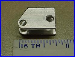
The link which connects the motor to the crank is a rather simple item, made from the same channel metal as the frame. As shown in the image, the link is about 3/4" long with one end square and the other cut back towards the closed edge of the channel. This end (left in the image) is also rounded with the hole closer to the open edge, to allow freer swing when attached to the motor arm. The square end has the hole nearer the center of the sides of the link. Both holes continue through both sides and are drilled with a 9/64" bit. This square end will connect to the screw coming from the paddle handle of the thumbscrew. The hole centers are 1/2" apart on my original, but you should make yours the correct length to allow a small amount of play at each end of the motor's stroke. Of course, this is also governed by the mounting holes for the motor.
Now we'll press the bearing into place in the bracket. There will be some interference with the screw head against the underside of the bracket surface. If the thumbscrew bends a little, we'll just bend it back after. Feed the screw through the bearing hole from above the surface and press the bearing into its hole. You may also wish to add an adhesive to this operation. Be sure to press the bearing in until the flange is seated all around. If you've used an adhesive, you can set this aside to cure.
Once cured you can pick back up with mounting the link onto the 6-32 screw through the thumbscrew. First check to ensure the screw is parallel to the centerline of the carriage bolt. If it isn't, adjust it; by bending, if necessary. Next, place one side of the square end of the link over the screw with the open side facing forward and the rest of the link toward the long end of the bracket. Start one of the nylon lock nuts onto the screw from inside the channel. Tighten until the screw starts to just protrude through the nut.
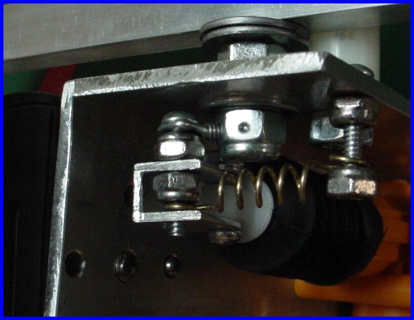
If necessary, adjust one end of the spring to fit over the screw with enough freedom that the nut won't interfere with the first coil. Place this end between the nut and the inside surface of the channel over the slight screw protrusion. Tighten the nut such that it pushes the screw through the opposite side of the link. Leave this nut a little loose so that the link and spring have plenty of freedom to swing.
Mount the actuator to the inside back of the bracket and place one of the 6-32 screws up through the link and mounting hole of the actuator arm. Tighten a nylon insert lock nut, upside down (as eplained in Note 2 above), onto the screw until it just cinches against the channel. The link should still be free to move on the arm.
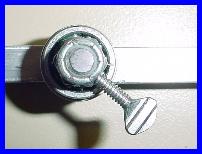
Move the frame back and forth to check for binding at the ends of travel of the arm, which should move freely into and out of the actuator housing. Place the nylon spacer on the 1/4-20 x 1-1/4" bolt and position the frame such that the thumbscrew is pointing toward the back of the bracket. Place the bolt through its hole (j) from the top and tighten one of the 1/4-20 hex nuts onto the bottom. The frame should now be limited to a 90 degree turn.
Place the last 6-32 screw through the bracket (hole a) and tighten the last nylon insert lock nut into place. Place the free end of the spring over the end of this screw and check for enough tension to pull the frame into each end of its travel. You may wish to use a longer screw if you'd like the spring to be perpendicular, and/or add a nut or drop of Epoxy to the end of this screw. I show a nylon lock nut, installed upside down in the closeup picture above.
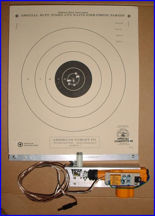
The last thing before we move to the cicuit is to make a cardboard backer and mount it into the channel. Use the last two 6-32 screws to secure the backer into the channel. Finally, set up the unit so you can use it to determine the components needed in the next section.
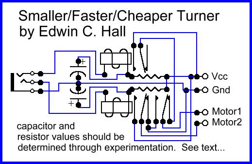
The purpose for this circuit is to provide a short burst of current only during the turn times, instead of a constant current in either direction, as well as to reverse the polarity to the motor to drive both directions. The reason I chose this approach is due to burning up several of these motors in early experiments. I don't know if these later motors would stand up to constant current or not, but I haven't lost any new ones using this circuit, thus far. I also consider it better practice to drain the battery as little as possible.
As to the electronics for this unit, I used a simple two relay circuit that switches the polarity and works off the discharge time for capacitors. Basically, the capacitors are charged, via the resistors, during the off time for the associated relay and that charge is what is used to energize the relay when switched by a ground on the opposite coil terrminal. The relay on time is the time it takes to discharge the capacitor through the coil. Unfortunately, this circuit has the inherent need for a charge time for the capacitors as well, which means the turner can not operate at Face or Edge times less than around two seconds. The resistors charge the capacitors, but also permit a current through the relay coils. If this current is too large the relays will energize (or stay energized when tripped), so the limited current means the capacitors charge more slowly, which is what limits the Face and Edge times. Although I've experimented with some other circuits to provide for shorter times, none of them has proved stable enough to use yet. They also added quite a few components to the circuit. I may still put in some time in this direction, but for now I'm going to stick with the shown design.
Now that I've given a rough description of the circuitry, I'll add in some more details and then describe how to determine the values for the capacitors and resistors. The values will be dependent on the relay used and the On time needed for the relay. The On time for the relay will be the time needed to complete the 90 degree rotation of the target and is determined by a combination of the current through the resistor and the current supplied by the capacitor discharging through the relay coil. The discharge is initiated by grounding the free end of the relay coil through the connector pin. This ground allows current flow from the capacitor (and resistor) through the coil, energizing the relay. Once the total current (that supplied via the capacitor plus that through the resistor) falls below that needed to hold the relay contact arm closed, the relay will de-energize.
The first thing to determine will be the minimum resistance that can be used to charge the capacitor without holding the relay energized. This will be slightly larger than the value needed to energize the relay. To find the best value, try to energize the relay with different value resistors in series with the coil. I would start with a value of 10k. Once you've determined the smallest value that won't energize the relay, test to see if this value can hold the relay if tripped by a smaller value. The "semi-final" test value should be the minimum usable resistance, but I would then use a value a couple of steps up from that for my final choice. After you have the resistance value chosen, you can move to the value for the capacitor. Here, I would start with an electrolytic with the value of 47uf 25VDC. (Be sure to observe the polarity and don't use a DC rating less than 25VDC.) The capacitance will be determined solely by the time the relay stays energized, which is going to be less than a second. What you'll need to do is balance the completeness of the turn with the shortest relay time. This may change with and without the backer in place, so experiment with the complete setup, rather than just the frame bar.
The last thing to decide is what type of connection to use for the control cable. You will need something with at least three conductors so you can have a common and two signals. A stereo audio connnector will work fine. You will then need the appropriate mating connector for the cable.
Once the circuit is completed, finalize all the connections and mount it. The turner should be finished at this time.
Your connecting cable will need to have at least three conductors. If you use a four conductor cable I suggest you double up the common connection with two of the four conductors. This will cut down the cable loss a little. Place your mating connector from the last step on one end of the cable and an appropriate connector for your controller or switching system on the other.
Note: You will need to determine the polarity of the connection based on the polarity of your charging system's coax connector!
Connect whatever device will provide Face and Edge signals and then connect the battery while watching out for the target if it should turn. Test both directions. You will need to allow time for the capacitors to charge if you use the described circuit. You should be able to get down close to two seconds for the charge time.
Note: A couple drill bits will be determined by what your tap suggests as the starting hole.