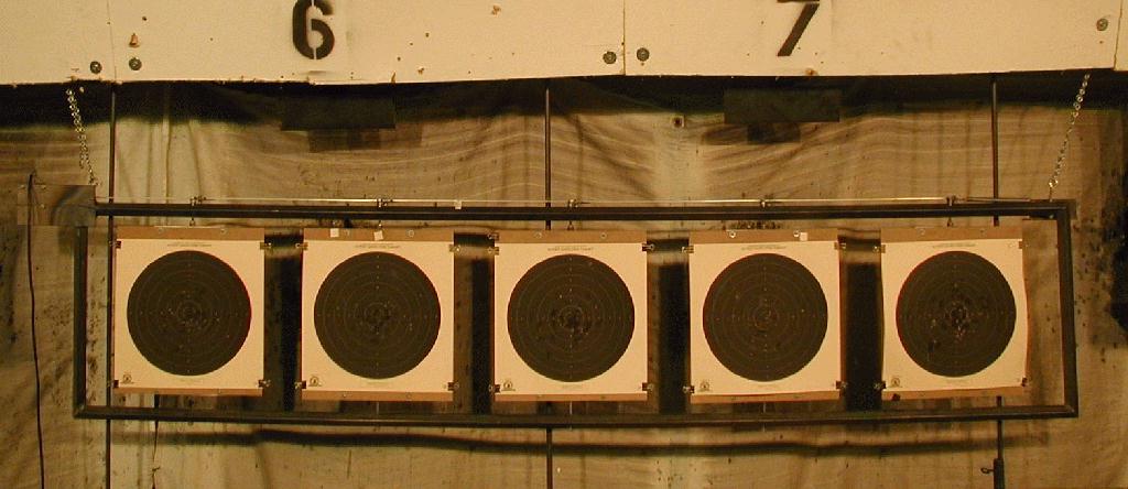
full view of five target portable Rapid Fire Bay - bay is hung in place for use
Back to Homepage
Here's a set of pictures showing how a Rapid Fire bay was constructed for the Arvada Rifle and Pistol Club in Colorado. This is actually one of two bays constructed. Although, these are dimensioned for International Rapid Fire Pistol, the concept would be fine for any other disciplines where turning targets are desired, simply by using the correct center to center spacing. The use of a solenoid makes the construction pretty straightforward and the actuation quick.
Thank you to R.M. for providing the pictures and initial description of this system via the TargetTalk Forum. His original post can be seen here, and another mention is made here. The following is the text of R.M.'s first post:
| With all of the talk about the expensive rapid-fire bays, I thought I'd pass my take of the situation. My home club is a 10 bay 50 footer. Bullseye is the main focus, but I've got them shooting a bit of International. For rapid-fire, we built a couple of portable bays. Quite cheaply actually. The framework's square steel tubing which hangs from chains. One person can carry it down range and hang it by himself. The push/pull is operated by electric solenoids/springs. Each bay cost in the neighborhood of $100.00 or a bit more. One of the guys built the timer, but one of the ones from TargetTimers will do the job too. Rapidfire bays need not be as expensive as one would think. You just have to be a bit creative and resourceful. For 6 or 7 hundred dollars, a club could have 2 bays with a timer. I know, for some clubs, that's a lot of money, but what you're getting is the ability to shoot one of the most fun matches going. I suppose even if your range is longer than 50', you could make one of these units and place it at 50'. If anybody's interested, I'd be happy to point you in the right direction in building one. I don't have the ability/knowlege to post photos of the unit, but could email them if anybody's interested. | ||
| R.M. |
This page includes the photos that were later added to the TargetTalk thread. Some have been edited slightly for this page. The originals can be found in the TargetTalk link. Additionally, some of these pictures are displayed smaller than the source picture. Therefore, if you save these images from this page to your computer, some will be larger than shown here.
Again, this will mostly be a series of pictures showing the project after it has been in operation, instead of a do-it-yourself project from start to finish. Some minor information is added along the way. If any discrepancies are noted, please let me know.
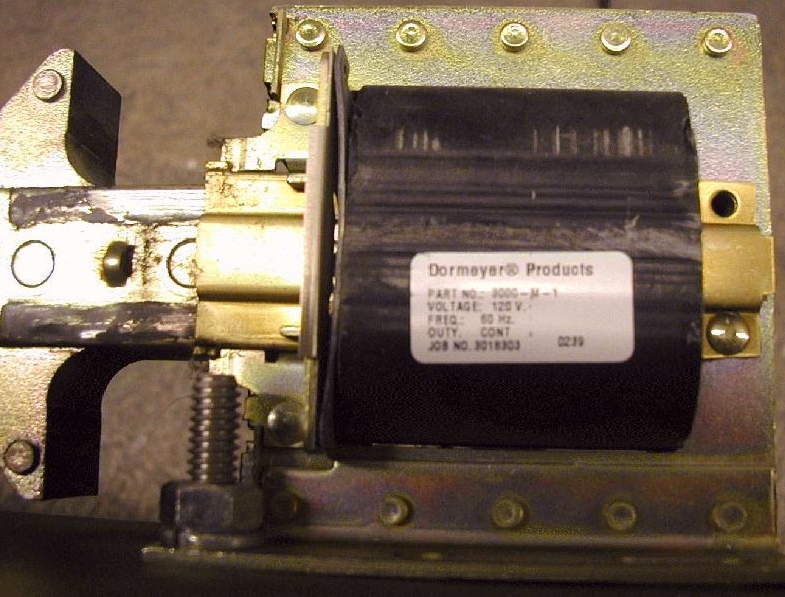
The solenoid shown in these pictures is what makes the system turn. It is run by supplying 120 VAC which causes it to contract, pulling the linking bar toward itself. The bar, in turn, pulls the five cranks which face the targets. At the opposite end of the bar is a return spring which moves the targets back to edge when the solenoid is released. The label is shown in this picture in case a like solenoid is desired for a similar project. In case it's difficult to make out in the picture, the part# is 3000-M-1. Some further research has been provided, including a source. This source mention is not an endorsement by this site or authors. It is merely a source that showed up through research: WW Granger. A search for "Item#" 4X242 will bring up the relay with specifications at the bottom of the item page.

The pictures above and below show how the linking bar is held by the solenoid. The solenoid is mounted to the back of a rectangular shield placed at the upper left corner of the bay. These views are from the back.

The above picture also shows the linking bar as it is mounted to target five and continues on to the other four.
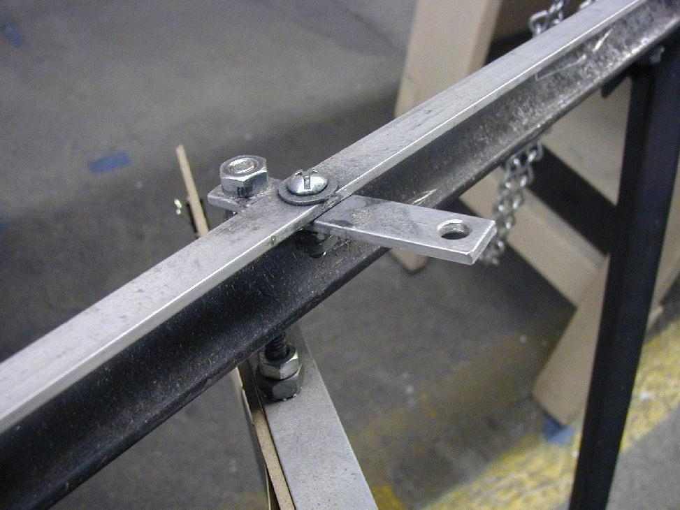

Here, a closeup is shown that includes the return spring at the end of the linking bar. Also note the brass bushing mounted into the tubular steel.

Here, above, is a closer shot of the construction of the lower pivoting point for target five. The other four targets are mounted the same. Note that for these targets hardboard is used to provide a rigid backing to allow for the bottom to turn solidly with the top of the target, which is driven.

Here, in the last picture, target five can be seen in its entirety. Note the upper left shield with the solenoid mounted on its rear. Also note the chain which is used to hang the bay when in use. When not in use the system is stored out of the way.

More on
target and
along with
solenoid
Secure
FTPS (SSL)
on the planet
Go FTP FREE