A Do-It-Yourself Multiple Turning Target System
Note 1: It is recommended to use the frame and motor setup from the ** NEW ** Do-it-Yourself Turning Target System instead of following the description given here. Then connect the link to the 1/4" inch bolt mounted in the end of the motor arm, as appropriate.
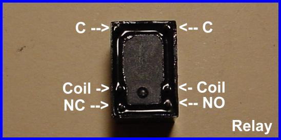
Note 2: A solenoid can be substituted for the motor system. Although a bit more costly, it can be made to turn the targets quicker and can be run from 120 VAC. A suggested solenoid for 120 VAC is the Dormeyer model 3000-M-1, which can be obtained through W. W. Grainger, Inc. using the part number 4x242. If you enter that number into the Grainger search block you can read the specifications for the relay.
Background
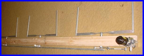
The multiple system was designed as an inexpensive turning system for ranges without the assets to buy a professional system. It is constructed of readily available materials and is made in a manner to allow (limited) portability. The construction is based on using a 2x4 as the main support for the turners. This 2x4 can then be mounted on a support structure at the 25 yard line by attaching the back surface to a sturdy framework. The dimensions for the one shown here are based on two-foot wide target frames mounted with centers three-feet apart. For different dimensions, appropriate changes are easily calculated. The one shown is a three-bay set built into an eight-foot 2x4. The motor used works fine for the three and indeed may even work for twice as many. This is something I will be testing soon.
The heart of this multiple turning system is the same windshield wiper motor as used in the individual system. It is described as a 2000-2001 Saturn L motor. Other types may work, but this one started turning up at surplus places for around twenty dollars. This type of motor has good torque and an integral switching system which can be used to limit the travel in one direction. Therefore, only one more switch is needed to limit it in the other direction. I found that for this alternate direction I also needed to provide a stop due to the inertia of the motor (and targets). The integral limiter stops the motor by reversing the polarity of the windings, but I didn't want to get that detailed in my construction of the other limit point. In the present design there is a relay which controls the direction of travel, the integral limiter for face position, and the added switch and bump stop for the edge position. The targets do have a "bobble" at the end of their swing, but they turn in a relatively quick fashion and the "bobble" ends pretty soon. The turning time is well less than a second, but is dependent on the weight of the system of targets.
This target system was designed to be faced by a momentary contact device such as a switch or relay. Such a signal is provided by my Rangebox, a command playback and switching controller powered by a 9-volt battery.
As with the individual system, I decided to place this information into the public domain so others can build them. If I can provide a means for someone to afford a turning system, then I'm happy to have published this page. If help or more information is needed, contact me (15 Lakeview Ave, Tupper Lake, NY 12986).
A list of materials I use is at the end along with some source information. Many of the parts are common type items found at many hardware stores, but some are from other places. For some of the "others," I've also provided part numbers. All of the frame and connection material is aluminum which obviously won't stand up to errant rounds. It is therefore suggested that a shield of some sort be provided as necessary. The shielding will have to be designed by the user and will of course add to the cost of the overall project.
Of course, no printed instructions can be free of a safety reminder these days. Due to the inability of me to be by your side through this, you will need to assume all risk involved with the construction and/or use of this system. This includes, but is not limited to, the use of all tools involved.
Updates
Feel free to provide feedback on how this project has worked. I will try to change it if better parts appear or techniques evolve. I have reviewed this document countless times, but there is no guarantee of accuracy. If an error is found, I will attempt to immediately get the correction out. Please feel free to send me comments.
Construction
For this unit, I'll break the steps down into preparing everything and then assembling the parts. The unit is actually quite simple in its workings with only a few items requiring any type of close tolerance, and even then, not that close. The steps along the way will include mounting bearings in the 2x4, cutting the connecting pieces, constructing the frames, building the motor bracket, wiring the motor and battery, modifying the motor arm and assembling everything. Do keep in mind that all the dimensions given here, such as for the switch mounting, are for the parts I use. Remember to make appropriate changes for the parts you have.
Step one - Mounting bearings in the 2x4
Special Note: For the sake of international readers who may not be aware of this, in the U.S. a 2x4 is merely a common name for a certain type of lumber. The lumber that is supplied by the lumber yard has been diminishing in size over the years. Currently, a "2x4" is actually 1.5 inches by 3.5 inches instead of the expected 2 inches by 4 inches. The length is normally correct, and all my measurements given will be correct for this unit.
- Choose an end of the 2x4 which will be used to mount the motor and measure 12 inches from that end for the first target frame. Place a mark on both 1.5 inch edges. Now measure 36 inches from that mark for the next. Repeat this for each target frame in your bank. When finished, you should have each mark centered at 36 inches from each other for all the positions of your bank. Create a centered cross mark at each location (3/4" from one of the edges) and ensure that corresponding marks are squarely located from each other. In other words, make sure that the two holes made for the bearings of each target are square with the 2x4 so that the target frames will sit squarely on it.
- Based on the outside dimension of the bearings you will use, and the length of any collar to be used, bore holes into the two edges for each location of a target. Cut these holes such that a bearing will be placed in each edge with a collar in between and the two bearings will be pressed against the collar by the through bolt and nuts. This should allow for the outside race of the bearings to be held by the 2x4 with the insides compressed against the collar by the rotating frame shaft. When boring the holes for the bearings a shoulder should be left to securely fix the bearings into the 2x4. In other words, cut a smaller hole for the collar leaving edges for the outer bearing races to be compressed against as the inner races are compressed against the collar. Also ensure that the inner races and collar are free to turn without dragging.
- Choose a top side for the 2x4 and cut a 1/4 inch deep by 2 inch wide notch across the bottom edge of the end chosen for the motor.
Note: This was not done in the original (pictured), but the original had a "spliced" motor arm piece which offset the arm by 1/4 inch.
- Mount the bearings with the collars in place for all the positions and set the 2x4 aside.
Step two - Preparing all connecting pieces
Note: The connecting pieces will consist of the channel aluminum which actually links all the targets together and the individual arms for each target. The lengths of these arms, or more correctly the distances between the centers of their holes, are what will determine the amount of turn for each target. The measurements I give will be based on the distance the motor arm travels in its 180 degree arc from Edge to Face. This dimension is one of the critical ones. I have built in an adjustment for each target to allow for the correct positioning at edge but this will not affect the degrees of rotation, so do pay attention to the dimensions given for the individual target arms.
- Mark a centered point on the back of the 3/8 inch channel at 1 inch from one end. Mark a second point 3 inches from the first. Mark a third point 36 inches from the second mark and then follow at 36 inch intervals for the rest of the target positions.
- Mill (or file) 1/4 inch by 1 inch slots into the back of the channel for each of these marked positions. Be sure to cut it in such a way that it leaves material on each side within the channel so that the modified nut placed inside will have something to grasp. See figure C1.
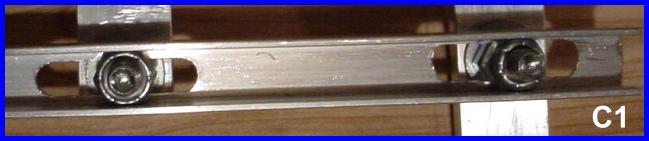
- Retrieve the 1/4-20 self locking nuts and modify them as follows. Grind down two opposite sides of each nut evenly, far enough that the nut is just narrow enough to insert into the channel metal. See figure C1.
- Cut a piece of 1/4 by 1 inch aluminum 3 inches long for each target frame (target frame arms). Cut one more piece 9 inches long (motor arm piece).
- For each piece of metal cut in the above step, drill a 1/4 inch hole centered 3/8 inch from one end.
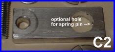
- For each of the target frame arms drill a hole whose diameter corresponds to the diameter of the carriage bolts that will be used for each frame. Place this hole centered and 2-1/8 inches (center to center) from the 1/4 inch hole. If desired, you can also drill a hole from the carriage bolt end through to the carriage bolt hole to allow for a pin to be used to prevent turning of the arm on the carriage bolt. A 3/32 inch hole and spring pin are recommended. See figure C2.
- For the motor arm piece drill a 1/4 inch hole centered 3/8 inch from the undrilled end.
- Set all these pieces aside for now.
Step three - Constructing the frames
- Cut a two-foot section from the 1/4 by 1 inch aluminum for each position. Also cut two one-foot sections of 1/4 inch channel aluminum for each position.
- Drill and square out a hole centered in the 1 inch aluminum pieces for the carriage bolts to sit fully within.
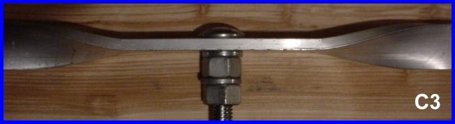
- Place a 90 degree twist in each arm of the 1 inch aluminum pieces two inches from the hole. The twist can take three or four inches. See figure C3.
- Choose an "up" edge for the 1 inch aluminum and drill a hole near this up edge in each end using a .107 inch drill bit. Make the holes .2 inch from both the end and the upward edge. Tap these holes to 6-32 threads. Round the corner of the aluminum to roughly follow the arc of the hole. Repeat with the other pieces.
- Take each one-foot section of 1/4 inch channel and drill a 9/64 inch hole .8 inch from one end and .2 inch in from the open edge. Drill the hole so it goes through both sides squarely.
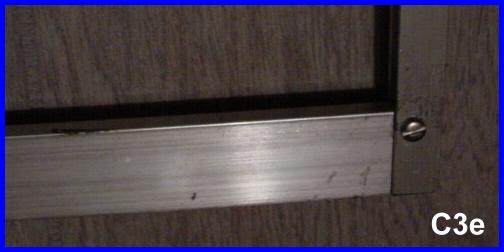
- Position a 1/4 inch piece of channel on each end of each of the 1/4 by 1 inch pieces and screw a 6-32 screw through each. The result should be an upright arm that can fold down along the base of the frame. Obviously it won't fold all the way because of the twist, but it should fold mostly down. In the upright position, the arms will be past square and you will need to adjust this by adding a small amount of glue of your choice to the gap between the 1 inch bar end and the inside edge of the 1/4 inch channel. I find hot glue works well for this. Place a 6-32 self-locking nut on each of the 6-32 screws and cut off the remaining threads of each screw if desired. See figure C3e.
- Place a carriage bolt through each piece of 1 inch aluminum and add a lock washer and a nut. Tighten the nut securely. Add a second lock washer** and another nut and tighten this nut securely. The double set will raise the frame above the 2x4 for clearance. See figure C3.
** Note: Depending on the distance you have between the bearings, you may need to skip this lock washer. If you still don't have enough room for the final nut when mounting the frame arms, you may even need to skip the second nut. Keep in mind the distance above the 2x4 that the frames will sit. If necessary, get longer carriage bolts.
- Set the completed target frames aside for later.
Step four - Making the bracket and modifying the motor arm
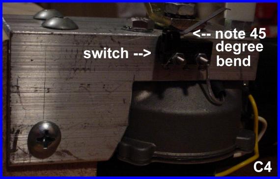
- Take the 2 inch by 2 inch by 4 inch long piece of angle aluminum and cut a square out of one side as shown in figure C4 to allow the edge of the motor to poke through. I know, my cutout isn't square. I didn't take enough out initially. If you prefer, you can cut yours like mine. {smile}
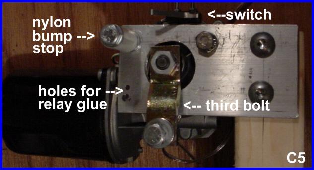
- Carefully measure and mark the three holes corresponding to the three mounting holes of the motor. The motor should be mounted in line with the bracket as in figure C5. One of the holes is under the arm in the picture. Drill these three holes with a 1/4 inch bit.
- Find the center between these three holes and mark and drill it with a 1-1/8 inch bi-metal hole saw.
- Mark and drill two 3/16 inch holes in this same side, 3/4 inch from the other end to be used to mount the bracket to the 2x4 as shown in figure C5. Make these holes 1/2 inch from their respective sides of the bracket.
- Mark and drill one 3/16 inch hole in the other side of the bracket 1/2 inch from both edges as shown in figure C4. This measurement should keep the mounting fasteners from striking each other within the 2x4.
- Drill two 3/32 inch holes 1/4 inch from the edge and 5/16 and 9/16 inch from the left side as shown in figure C5. These measurements are not critical. The holes will be used to help hold the glue for the relay.
- Drill two 3/32 inch holes 1/4 inch from the edge, and 1-1/4 and 1-5/8 inches from the side with the cutout (right edge in figure C4). These holes will be used to mount the limiter switch as shown in figure C4.
- Using hot glue (my preference) or a glue of your choice mount the relay under the edge of the bracket making sure it isn't going to interfere with the mounting of the motor.
- Place two 2-56 screws with lock washers through the holes for the switch from inside and tighten two 2-56 nuts onto the outside.
- Being VERY CAREFUL bend the lever of the switch up at about a 45 degree angle at a point just past the switch contact as shown in figure C4. Don't put any sideways pressure on this switch - it will break.
- Slide the switch over its mounting screws and tighten one lock washer and nut onto one of the screws. Leave the other off for now.
- Remove the arm from the motor and keep the original lock washer and nut. Cut the ball off squarely at the shoulder, about .1 inch above the surface of the arm.
- Drill the center of the base where the ball was with a 3/16 inch bit. Tap this hole with a 1/4-20 tap. Try to be as square as possible with this tapping.
- Fully tighten against its shoulder, one of the 1/4-20 bolts into the newly tapped hole from the cut side.
- Cut the excess bolt off even with the underside of the arm.
- Set the arm and its modified bolt aside for now.
Step five - Wiring the bracket and motor
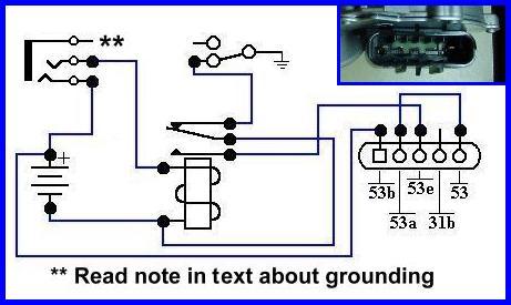
Note: The connections on the bottom of the motor will be referenced by the numbers given on the connector housing. In case you get a motor which has different markings, this can be a key: A=53b, B=53a, C=53e, D=31b and E=53. A-E will be from the left looking into the connector with it on the bottom and the shaft pointing upward.
Note: You can use some of the speaker wire from the 100 foot spool for these connections. You will only need about 80 feet to connect your target bank for 25 yard use. These connections will use less than five feet.
** Special Note: The shield of the 1/4 inch connector must not be attached to the bracket, motor or framework in any way. For this unit I have suggested an inline connector. You could alternately use a panel type mounted to the wooden 2x4 as long as there is no physical contact with the motor or bracket. This would cause an overcurrent during the face operation.
Step six - Wiring up the battery and the connecting cable
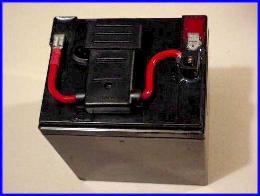
Note: I reference 3/16 inch connectors below for the battery. If your battery has 1/4 inch connectors, substitute appropriately below.
- Remove the plastic insulator from one of the 3/16 inch quick connect female terminals and crimp and solder it to the positive (outside) connection of the female coax connector.
- Cut the fuse holder leads to length and solder one lead to the center pin connection of the coax connector.
- Crimp a 3/16 inch quick connect female terminal onto the other lead of the fuse holder.
- Push the terminal mounted to the coax connector onto the positive terminal of the 12 volt battery.
- Push the remaining fuse holder terminal onto the negative terminal of the 12 volt battery.
- Install the 5 Amp fuse in the holder.
- Using the glue of your choice (I use hot glue) secure the coax connector to the battery.
- Strip both ends of the remainder of the 100 foot spool of speaker wire and install the 1/4" plugs connecting one lead to the tip and the other to the shield. Note: If the controller you are using has a different style connector, install the appropriate connector on that end of the cable.
Step seven - Testing and setting up the motor
Note: The arm should not be on the motor yet. If it is, remove it for these tests.
- First, clamp the motor bracket to something solid so it won't move around as you test it.
- Momentarily plug the motor power connector into the battery connector. The motor should spin counterclockwise (CCW) looking at it from the end of the shaft.
- With the motor turning, depress the lever of the switch. The motor should stop turning.
- Release the switch and let the motor run CCW.
- Short the tip to the sleeve of the 1/4 inch connector. This should cause the motor to reverse direction and travel for only a short arc where it comes to an abrupt stop. Remove and replace the short several times to get a feel for how the motor works.
Note: This next step is very important to the proper operation of the unit. You may need to perform this step several times to be sure it's correct.
- Once you're familiar with how the motor stops in its clockwise rotation, cause it to reach its stop point and leave the short in place on the 1/4 inch connector.
- Unplug the power connector from the battery.
- Place the motor arm over the shaft and loosely rotate it around its arc. Check that it does not rub against the inside of the 1-1/8 inch hole cut through the bracket. If rubbing occurs, grind down the areas of the arm that touch until the arm will have enough clearance.
- Apply a small amount of Loctite to the contact area of the motor arm and shaft and place the arm onto the shaft so it is facing perpendicular to and away from the back edge of the bracket. This will place it directly over one of the motor mounting bolts and CCW about 120 degrees from the nylon bump stop (see figure C5). Using the original lock washer and nut, tighten the arm onto the shaft.
- Set the assembly aside for the Loctite to cure.
Step eight - Assembling everything
- Retrieve the 2x4 and insert the carriage bolt of one of the frames through the first set of bearings from the motor end of the 2x4. Tighten a nut onto this bolt drawing the bearings against the internal collar.
- Add a lock washer to the bolt and then add one of the frame arms. Add another lock washer and the final nut. Orient the 2x4 such that the motor end is to your right and you are looking directly at the end of the carriage bolt. While holding the frame centered and parallel with the opposite edge of the 2x4, and the arm 45 degrees CCW from 12 o'clock vertical, tighten the final nut. See figure F1.
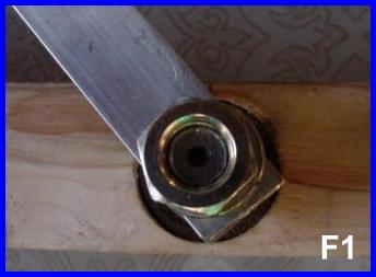
- Repeat this step for all the other positions.
- Mount the motor so that it sits as shown in figure C5. I suggest using the 3/32 inch drill bit to make pilot holes in the 2x4 to help prevent splitting of the wood. This positioning should place the motor arm pointing parallel with the 2x4 toward the frames and the motor itself on the same side of the 2x4 as where the frame arms are pointing.
- Place a 1/4 inch flat washer onto one of the 1/4-20 bolts and place the bolt through the first frame arm. Add the second flat washer and tighten on a second nut against the shoulder of the bolt. With this nut tightened the bolt should spin freely within the hole of the frame arm. Screw the bolt through the appropriate position in the channel aluminum into one of the modified self locking nuts. Secure, but do not tighten fully yet.
- Repeat for all other positions.
- Retrieve the 9 inch motor arm piece and place a 1/4-20 bolt with two washers through one end in the same manner as with the frame arms and tighten with a nut: bolt - flat washer - arm - flat washer - nut. Again, the secured bolt should spin freely within the arm piece.
- Screw this bolt into a modified self locking nut through the remaining slot of the channel metal.
- Place a flat washer on the modified 1/4-20 bolt and place it through the free end of the motor arm piece. Add another flat washer and tighten the bolt into the motor arm. The motor arm piece should remain free to move on the bolt and the bolt should not protrude from the underside of the motor arm.
- Align the frames parallel and centered with the 2x4 and tighten all the fasteners through the channel metal. The ability to slide the modified nuts and respective bolts within the slots should allow for all the frames to be positioned correctly.
- Once all alignments are complete, unscrew the bolt connecting the motor arm piece to the motor arm and apply a small amount of Loctite. Retighten the bolt.
- Optional:. If you drilled the holes for the spring pins in the motor control arms, you should now drill the bolts via those holes and insert the pins. I suggest drilling only a minimum depth and using overlength pins so that there is enough pin still left out to get ahold of in case you have to remove an arm.
Final Testing
Cautionary Note: When working with this target system take into account how far the frames will turn when moved to the edge position. Be sure to be outside this radius when testing and using the system. The frames will turn with enough force to cause injury. Also ensure other objects are outside this radius.
- Mount the 2x4 to a solid backplane by placing it against the support leaving enough space for all moving parts to move unobstructed.
- While staying outside the radius of the targets and away from the moving parts, connect the battery and whatever device will provide a signal to the 1/4 inch jack and test the system. The targets should now turn relatively quickly. They may "bobble" a bit at each end of travel. You may need to adjust the frame arms in the channel to get the best edge condition. Be sure the motor stops at both positions. If a controller is not readily available, you should be able to activate the face position by shorting the connector at the controller end of the cable.
Tools and Materials List:
Note: Throughout the above document I was vague on what size some of my chosen parts were. This is because you may choose a different size. In the parts and tools lists I have placed the descriptions and sizes I used within square [] brackets after the part.
- countersink cutter (optional - I use this to chamfer the holes)
- large crescent wrench - I use this to twist the frame crosspiece
- small crescent wrench
- tape measure
- calipers
- square
- 3/32 inch drill bit
- .107 inch drill bit
- 9/64 inch drill bit
- 3/16 inch drill bit
- 1/4 inch drill bit
- Dremel set (optional)
- appropriate drill bit for your carriage bolts [1/2 inch]
- appropriate wood drill bit for mounting the bearings into the 2x4 [1-1/8 inch]
- appropriate wood drill bit for mounting the collars between the bearings in the 2x4 [7/8 inch]
- 1-1/8 inch bimetal hole saw
- milling bit to cut the 1/4 inch slots in the 3/8 inch channel aluminum (a file can be used)
- SAE 6-32 tap
- SAE 1/4-20 tap
- 10mm socket or wrench
- 7/16 inch socket or wrench
- drill - a press would be a definite advantage but a hand drill may work
- wood saw
- hacksaw
- vise
- C-clamps at least two
- grinder - wheel for drill is OK, but a bench type is better
- triangular file
- flat file
- round file
- small hammer
- screwdriver appropriate for your 6-32 screws [flat tip]
- soldering iron
- terminal crimpers
- hot glue (w/gun) or epoxy
- Loctite red (#271) or blue (#242)
- solder
Parts List: (Source and P/N of part)
Note: Some of the parts I used for this project came from All Electronics. I am in no way affiliated with them other than being a customer. There are several other sources for many of these parts or similar. I provided this list with All Electronic part numbers solely for your information. Feel free to use alternate vendors. For items without part numbers, these should be readily available from hardware stores.
-----------end of list--------------